Wednesday, December 7, 2011
Tuesday, December 6, 2011
Calculation Model Error
The model we used to calculate the constraints on our machine can be found here. Since there are so many variables that can be modified according to changes in our design, we varied some while keeping others constant as physical restrictions. One of these constants was mass, which is listed as 5kg (approximately 11 pounds) according to the attached model. The calculations of required motor torque, acceleration, and maximum velocity depend on this value. After actually creating our robot, however, the total mass was measured to be around 8 pounds. This significantly reduces the validity of our calculations. Because we neglected to consider a range of possible masses instead of one sample mass we significantly overestimated the previously mentioned key parameters of our system. As a result (and as stated in our last post) we are unable to push the tower as originally planned. The frictional force on the wheels accounting for the propulsion of the vehicle is not high enough to overcome the frictional force acting on the tower. A slipping of the wheels occurs because of this fact, disabling this part of the robot's functionality.
Our Last Efforts
After weeks of hard work in the machine shop, our machine is complete. While by no means was it a smooth ride, full of last minute issues and seemingly impending doom, the robot Awesom-O is fully functional and, with a few tweaks in strategy, ready for a stellar performance in competition.
In summary, the final function of our robot was to trap balls on the table using the shown arms with crossbar, and to drive them to the goal while being guided by the bead rails and bent-over plate. The two metal motors provided plenty of torque to complete the driving during this task and allowed for easy turning. The 6-speed motor driving the arm bar also had sufficient torque to make the movement controllable in competition. The following is a description of the final problems we encountered, as well as techniques and decisions we used to complete our machine for competition.

The main problem that we faced in manufacturing our robot was coupling our motors to the shafts that they needed to power. For the six speed motor, the one powering the arm that captures balls and that pushes the tower, we used plastic tubing connected to a brass coupling from a motor kit, secured with pins. This proved to be an effective method, although the tubing added a slight lag when controlling the arm.

For the metal motors, we manufactured a small aluminum coupling that connected the motor to the gear that drives the shaft. It took two attempts to make such a precise piece, but we were able to manufacture an effective coupling. The gear was fit onto the smaller end of our aluminum coupling and secured with a pin. The other end of the coupling, which was attached to the motor itself, was secured with a set screw. While very concerning at first, our homemade couplings proved to be sufficient.
There were also several additional components that we added to our design after testing it on the playing table. First, when driving into balls, we found that the rubber ones in particular would catch on the underside of the front edge of the machine. To remedy this issue we added an aluminum cover to the front edge of the machine. This prevented the edges of the machine from digging into the rubber of the balls and allowed us to smoothly capture balls of any kind.

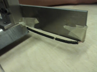
We also found however, that the rubber balls were catching on the underside of the containment side rails. This posed a more difficult problem because it is not possible to immediately remedy this situation. It unfortunately came to a decision where we had to choose where we wanted to lose points. We created rails of beads that would allow us to collect the balls without a problem, but the only way that we could attach them as an afterthought like this would be with glue (shown below, temporarily attached with tape), which is not a great design and manufacturing technique. We therefore had to choose between losing points for not being able to easily collect all the balls, or losing points for poor design. Our decision was made last minute to include the bead rails after talking with the GSIs.

In summary, the final function of our robot was to trap balls on the table using the shown arms with crossbar, and to drive them to the goal while being guided by the bead rails and bent-over plate. The two metal motors provided plenty of torque to complete the driving during this task and allowed for easy turning. The 6-speed motor driving the arm bar also had sufficient torque to make the movement controllable in competition. The following is a description of the final problems we encountered, as well as techniques and decisions we used to complete our machine for competition.

The main problem that we faced in manufacturing our robot was coupling our motors to the shafts that they needed to power. For the six speed motor, the one powering the arm that captures balls and that pushes the tower, we used plastic tubing connected to a brass coupling from a motor kit, secured with pins. This proved to be an effective method, although the tubing added a slight lag when controlling the arm.

For the metal motors, we manufactured a small aluminum coupling that connected the motor to the gear that drives the shaft. It took two attempts to make such a precise piece, but we were able to manufacture an effective coupling. The gear was fit onto the smaller end of our aluminum coupling and secured with a pin. The other end of the coupling, which was attached to the motor itself, was secured with a set screw. While very concerning at first, our homemade couplings proved to be sufficient.

There were also several additional components that we added to our design after testing it on the playing table. First, when driving into balls, we found that the rubber ones in particular would catch on the underside of the front edge of the machine. To remedy this issue we added an aluminum cover to the front edge of the machine. This prevented the edges of the machine from digging into the rubber of the balls and allowed us to smoothly capture balls of any kind.

We also found however, that the rubber balls were catching on the underside of the containment side rails. This posed a more difficult problem because it is not possible to immediately remedy this situation. It unfortunately came to a decision where we had to choose where we wanted to lose points. We created rails of beads that would allow us to collect the balls without a problem, but the only way that we could attach them as an afterthought like this would be with glue (shown below, temporarily attached with tape), which is not a great design and manufacturing technique. We therefore had to choose between losing points for not being able to easily collect all the balls, or losing points for poor design. Our decision was made last minute to include the bead rails after talking with the GSIs.

We also encountered difficulty when driving because of how front loaded our machine is. We were initially not even able to drive over the hinges on the table. To fix this problem we manufactured a heavy name plate that was attached to the rear of the machine to weigh it down, which fixed the problem and also added to the visual appeal of our design.

Unfortunately, during testing, we also found that we could not push the tower. We had to gear up our metal motors in order to provide the necessary torque to push the tower, but the cheap plastic gears that were provided for our use simply cannot support such power. When we try to push it they just begin to grind down and destroy themselves. Given metal gears, pushing the tower would be feasible with our design, but for the competition, it does not appear that we will be incorporating a tower push in our strategy. Luckily our design is versatile, and we will most likely play to score first and play defense from there on out.

Thursday, December 1, 2011
Trade Notice
We have traded our nylon rack ($2.98) for two 48 D.P.,24 Teeth, 20° Pressure Angle, Acetal/No insert spur gears ($1.33). The value of our piece was worth 32 cents more than the items that we received.
Tuesday, November 29, 2011
Trade Notice
We have traded our 3/8" diameter aluminum rod ($2.44) for another 1/4" diameter aluminum rod ($2.31). The value of the rod we traded in is 13 cents more than the rod we received.
Wednesday, November 23, 2011
Machine Manufacturing Update
As of today, our team walked out of the water-jet lab with two freshly cut diagonal bars and vertical bars. The diagonal bar's ends, however, were not fully cut off, and still attached to the main shaft. This was a result of slight water-jet complications pertaining to the type of bar we needed to be cut (1"x1" hollow square tube) and slight carelessness of the water-jet operator. It is important to understand that the cut path was programmed into the water-jet correctly, but the edge finding was carried out by the operator by approximation and not with an actual edge finder. Furthermore, because the tube was hollow, the physical geometry of the tube meant that the water jet would be cutting through two different thicknesses. At the ends, the depth of the cut was a full 1" while the inside had a thickness of 1/8" (on top and bottom) so a total of depth of 1/4" was required. The water-jet operator combated this feat by cutting the thicker part of the tube at a slower feed rate while the inside of the tube was cut at a faster rate. After the cutting process, the neglect of edge finding resulted with an incomplete cut on one side. Luckily, the uncut length was less than 1/8" and the solution for removing the unnecessary stock was using a band saw as well as a file to smooth out the surface area to specification. On a positive note, the cutting of the vertical bars was done correctly.
Subscribe to:
Posts (Atom)